Electric Motors
Introduction
- Electric Motors Convert Electrical Energy into Mechanical Rotational Energy
- As the name implies, they make use of electrical input to create motion
- Using the interaction between electrical & magnetic forces, they manipulate the rotating & non-rotating components
- They may use magnets, windings or solid sections
- The rotating component of a motor is called Rotor
- The stationary component of a motor is called Stator
- If the rotor is present on the inner side, it is called an In-runner motor
- If the rotor is present near the outer circumference of motor, it is called an Out-runner Motor
There are 5 types of motors that we will discuss,
- [[#AC 3 Phase Induction motor]]
- [[#BLDC Motor]]
- [[#Permanent Magnet Synchronous Motor (PMSM)]]
- [[#Synchronous Reluctance Motor (SynRM)]]
- [[#Switched Reluctance Motor (SRM)]]
AC 3 Phase Induction motor

- Works on principle of Electromagnetic Induction based on the Lorentz Principle
- Lorentz force, the force exerted on a charged particle q moving with velocity v through an electric field E and magnetic field B. The entire electromagnetic force F on the charged particle is called the Lorentz force (after the Dutch physicist Hendrik A. Lorentz) and is given by
F = qE + qv × B
- The stator has 3 pairs of windings arrange 120º apart from each other
- Each of them are energized with separate phase AC supply, each of the phases are 120º out of phase to the other.
- This ensures that at a time 1 phase is at peak +/-ve amplitude, the other 2 are at intermediate levels
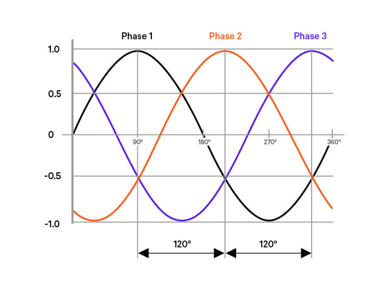
AC 3 Phase induction motor
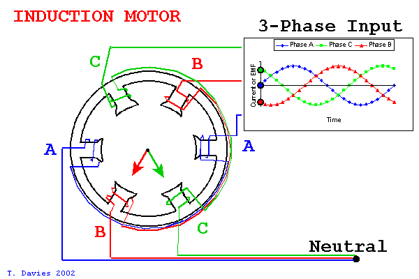
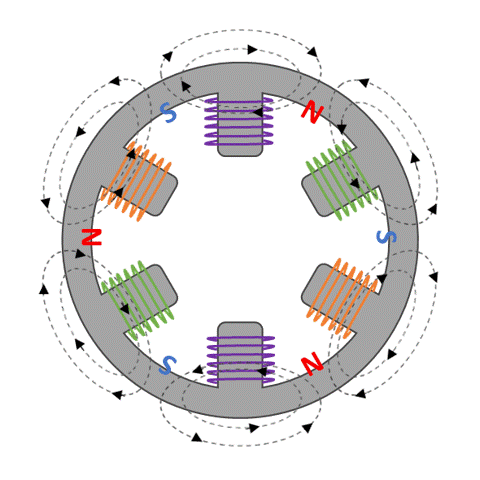
- This ensures that only 1 winding pair will be fully activated at a time.
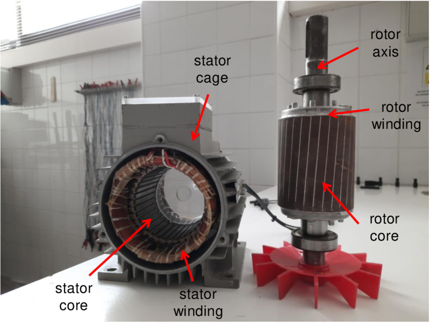
- The stator field windings will generate a magnetic field which will cause an electromagnetic induction of current in squirrel cage
- The squirrel cage will act like a winding since the ends of each rod are shorted to the end plates
- This will create virtual winding pairs in the squirrel cage in which current will be induced
- When current flows through a conductor, a magnetic field will be set up inside that conductor
- Therefore, the current induced inside squirrel cage will cause a magnetic field to be set up in the squirrel cage as well
- This magnetic field will be attracted towards the stator windings, which are energized in the direction of motion
- The squirrel cage will therefore start to follow the stator windings being energized
- It will always follow and never reach in sync with stator energization, hence AC Induction motors will always have some slip at no load conditions as well.
- Since current is induced in the motor, the name AC Induction Motor is derived
- In order to strengthen the magnetic field generated by squirrel cage, a magnetic core is inserted inside to be temporarily magnetized by squirrel cage's magnetic field while in operation
- This will generate more torque and reduce power requirement, thereby increasing efficiency of motor
- In order to reduce losses due to eddy current, the cross sectional area of the iron core is reduced by splitting the core into a series of iron discs/plates separated by insulating layers
- AC motors do not need position sensors in order to work as motor will dynamically adapt to load conditions as rotor tries to follow stator windings being energized.
- Usually, the applications require constant speed output. Ex: Pumps, Spinning & Grinding Mills, et
- In case speed control is required, a [[#Variable Frequency Drive (VFD)]] is used.
- It will be discussed in detail at a later point in this module
DC Motor
Video
Click or Scan QR Code to view video on Brushless DC Motor
https://www.youtube.com/watch?v=CWulQ1ZSE3c
BLDC Motor

- BLDC is an evolution of the Brushed DC Motors
- As the name suggests, they work exclusively on DC power
- In brushed DC motors, the commutator brushes wear over a period of time
- BLDC eliminated the use of brushes by carrying out commutation using electronics
- It works on the magnetic principle of attraction & repulsion of magnetic poles
- There are permanent magnets situated on the rotor.
- There are phase windings present on the stator
- The stator has multiple winding pairs. They are exciting systematically, such that, at a time, the winding is attracted to the pole closest to it in the direction it is rotating
- This attraction between unlike poles (N-S/S-N) will generate a torque as winding move closer to magnet
- Once winding reaches magnet, torque becomes zero, at this instant, winding is depowered and the next winding is energized to cause it to travel to magnet
- By connecting 2 windings in series, one can take advantage of the repulsive forces created by like poles (N-N/S-S), which will push/repel the winding away from like magnetic pole.
- This will simplify the winding energizing, as at a time only 1 signal is to be sent to power motor
- It will also boost torque, and smooth out the torque output curve.
- The activation of each phase winding is carried out by the controller, in order to activate the windings correctly with load, a position sensing feedback system is to be included
- A hall sensor is used for this purpose, it will relay position of rotor to controller which will accordingly adjust output by increasing/reducing/keeping constant the speed.
- Speed control is achieved by modulating the voltage pulse amplitude and current output
BLDC Commutation Interactive Element
To see how your own BLDC motor's Electronic Commutation Switching is going to work, Click here
Permanent Magnet Synchronous Motor (PMSM)

- They work by ensuring the synchronicity between rotor & stator.
- There will be 0 slip between them, and both rotor & stator will move a same speed - which is the synchronous speed (
) - An AC coil is present on the stator which generates a rotating magnetic field
- On the rotor, permanent magnets are placed, hence the name Permanent Magnet Synchronous Motor
- Instead of a permanent magnet, one can also use a filed winding with DC excitation, it will also behave like a permanent magnet since field is constant
- The permanent magnet field inside rotor is attracted towards the magnetic field generated by AC winding excitation in stator.
- The rotor will magnetically synchronize itself with the rotating magnetic field in stator winding, hence called Synchronous Motor
- These motors are not inherently self starting
- Therefore, they will need a position sensor for feedback & control
DC Winding Rotor Self- Starting
- A Synchronous Motor with DC winding rotor can be made to self start by adding a squirrel cage to the rotor
- During initial starting phase, the DC windings are not excited.
- Thus, the AC field windings induce current in the squirrel cage and motor starts spinning like an AC induction motor
- As we know, there is always some amount of slip in AC induction motors, that is rotor is always lagging behind stator winding excitation
- Rotor speed is less than synchronous speed (
) - Therefore, once motor reaches maximum speed possible, the slip/load angle between rotor and stator becomes as small as possible, at this instant, the DC windings are charged.
- This causes the rotor to now synchronize itself with the stator fully to attain no slip position.
- At this position, since the squirrel cage bar will move in sync with stator excitation, there is no more current induced in the bars.
- Hence DC winding takes over the task of rotor's spinning motion completely.
PMSM Starting
- Unlike the DC winding, one cannot turn on/off permanent magnets, hence another method is to be devised to start this motor
- AC field excitation at synchronous speed (
) is too fast for the magnetic rotor to latch on & synchronize. - The magnetic pole of AC field has already passed and the opposite pole has come next to the magnet
- This happens because of the inertia of the rotor due to its weight
- If the AC field windings were to be sufficiently slowed down, the magnetic rotor will enough time to latch & synchronize with rotating AC field winding excitation
- Once, rotor synchronizes and reaches same speed as stator, speed can now slowly be increased till max speed is reached
- In order to control and vary rotating AC field winding speed, a [[#Variable Frequency Drive (VFD)]] is used.
PMSM Regen Interactive Element
To see how your a PMSM in car will work with Regen, Click here
Synchronous Reluctance Motor (SynRM)

- Works on the principle of magnetic [[#Reluctance]].
- As the name suggests, these motors are synchronous as well.
- In the stator, a rotating magnetic field will be produced by AC field winding excitation
- The rotor will have a series of stamped sheets stacked together in a bunch
- The design of the cutouts on rotor is such that they have 2 distinct positions, 1 position with maximum flux density and another with minimum flux density
- This ensures that rotor will not tend to lag or lock while spinning in synchronization
- The rotor will find the position of least reluctance with magnetic field generated by AC windings and move at same speed with it, that is, at synchronous speed (
) - This motor is also not self starting and hence utilizes a VFD to slowly speed up the rotor from 0 to max RPM
- Since these motors are not inherently self starting, they will need a position sensor for feedback & control
Switched Reluctance Motor (SRM)

- According to the [[#Reluctance]] principle, the magnetic flux always tries to flow through the minimum reluctance path, just as the current tries to flow in the minimum resistance path.
- Hence the reluctance between the stator poles and rotor poles is varied, and the rotor tries to align itself in the minimum reluctance axis. In this process, a variable reluctance torque is produced, which rotates the rotor.
- Rotor is a solid core with slots cut into it to create poles
- The stator has field windings which are switched on & off and also polarity of switched to reverse poles over and over.
- A typical SRM will have a 6 pole stator and 4 pole rotor, this ensures that at a time, only 1 reluctance position is there
- Once a winding pair is energized in the stator, it will create its own minimum reluctance paths, the rotor will realign to this position of least reluctance
- As soon as rotor reaches that position, reluctance torque becomes zero as the rotor has achieved its position of least reluctance
- In order to have continuous motion of rotor, at this point a new winding pair is energized and the current pair is de-energized
- This will create a new minimum reluctance position inside the rotor will move to realign itself in that position
- Since this motor is not inherently self starting, it will need a position sensor for feedback & control
- A controller will regulate sped and input signaling to the motor based on input & load conditions
- Since a switching circuit reverses the polarity, a DC supply is provided to this motor.
- By modulating the voltage & current pulse amplitude, speed can be increased on decreased
Variable Frequency Drive (VFD)
- The synchronous speed (
) of a AC field winding is derived from the following equation
Formula
Where,
f = Frequency of AC excitation in Hertz(Hz)
P = No. of poles on stator
- Here we can see that
is a function of the 2 variables - 1. frequency and 2. stator poles. - The poles on a stator are non-variable since one cannot easily add or remove poles to an already existing motor
- Therefore, the only variable that we can realistically change is the frequency of supply
- The VFD as the name suggests will vary the frequency to being about a change in the speed at which the rotating magnetic field will rotate
- When using VFD to start motor, initially frequency will be set as low as possible to set rotor in motion, once rotor is in motion, the VFD will gradually increase frequency
- This will cause
(Synchronous Speed) to also gradually increase - The VFD will keep increasing frequency till maximum frequency & speed limit is reached
VfD Interactive Element
To calculate your own direct Drive motor's VfD Characteristics, Click here
Reluctance
- It is analogous to the electrical resistance found in flow of electrons.
- Similar to it, the resistance a magnetic flux faces while travelling through a medium is called Reluctance.
- The SI unit for its measurement is Henry(H)
- One can easily see the reluctance paths when one drops iron shavings/filing on a flat white sheet of paper and then place a magnet on it. The iron particles will always rearrange themselves to form a particular shape as shown below.

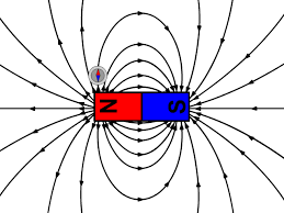
- The reluctance values for various materials are different.
- The path of least reluctance is where magnetic resistance is found to be very less. More flux density will be found here as this is the easiest path for magnetic lines to pass through
- The path with higher reluctance will therefore have lower magnetic flux density.
- In case of air and iron, the reluctance of iron is much less than air, therefore magnetic flux lines will prefer to pass through iron rather than air
Conclusion
- The above types we discussed are all based on the radial flux design where flux direction is perpendicular to axis of rotation.
- Another emerging technology is the Axial Flux Motors where flux path is parallel to axis of rotation.
- It opens up a few new paths that we can explore in motor design
Motor Comparisons
| Motor Type | Efficiency @ Constant RPM | Current Rise w/ Torque (Constant RPM) | Current Rise w/ Torque (Top Speed) | Cost | Flux Density | Torque Density | Control Complexity | Key Pros | Key Cons | Example in India |
|---|---|---|---|---|---|---|---|---|---|---|
| PMSM (Interior or Surface) | ⭐⭐⭐⭐ High | Linear | Exponential | 💰💰💰 (High – Rare earth magnets) | ⭐⭐⭐⭐ (High – due to magnets) | ⭐⭐⭐⭐ (Excellent) | ⭐⭐⭐ (Needs FOC + rotor position sensor) | High efficiency, great torque, compact | Costly, magnets degrade at high temps | Tata Nexon EV, MG ZS EV |
| BLDC (Trapezoidal) | ⭐⭐⭐ Moderate–High | Step-wise | Steep rise | 💰💰 (Moderate) | ⭐⭐⭐ (Good) | ⭐⭐⭐ (Good) | ⭐ (Simple, Hall-based) | Cost-effective, good for light EVs | Torque ripple, less smooth | Ather 450X, Ola S1 |
| IM (AC Induction) | ⭐⭐ Medium | Non-linear (slip dependent) | Gradual rise | 💰 (Low – No magnets) | ⭐⭐ (Moderate, field-oriented) | ⭐⭐ (Low–Medium) | ⭐⭐⭐⭐ (Well-known control) | Rugged, cheap, no magnets | Less efficient, heavier | Mahindra eVerito, older Tesla models |
| SRM (Switched Reluctance) | ⭐⭐ Medium | Abrupt/Non-linear | Very steep | 💰 (Very Low) | ⭐⭐ (Depends on design) | ⭐ (Low) | ⭐⭐⭐⭐ (Highly complex, high-frequency control) | Simple construction, no magnets | Noisy, torque ripple, EMI issues | Prototype/R&D, commercial 3W |
| SynRM (Synchronous Reluctance) | ⭐⭐⭐ High | Smooth, mild non-linear | Steep | 💰💰 (No magnets, but needs special rotor design) | ⭐⭐ (Moderate) | ⭐⭐ (Less than PMSM) | ⭐⭐⭐⭐ (FOC + rotor position estimation) | Magnet-free, efficient | Lower peak torque, still emerging | Hyundai R&D, future EU/India tech |
Legend:
-
⭐ = Rating (1–4)
-
💰 = Relative cost
-
FOC = Field-Oriented Control
-
EMI = Electromagnetic Interference
EV Motor Type Comparison Table
| Parameter | Permanent Magnet Synchronous Motor (PMSM) | Switched Reluctance Motor (SRM) | Synchronous Reluctance Motor (SynRM) | Brushless DC Motor (BLDC) | AC Induction Motor (IM) |
|---|---|---|---|---|---|
| Operating Principle | Uses permanent magnets on the rotor and synchronized stator field | Uses rotor saliency and reluctance torque with switched windings | Uses rotor saliency to generate reluctance torque | Uses permanent magnets with trapezoidal commutation | Uses electromagnetic induction with squirrel cage or wound rotor |
| Efficiency | Very high ~95% | Moderate (85–90%) | High ~90%) | High ~90%) | Moderate ~85%) |
| Torque Density | High | Moderate | Moderate | High | Moderate |
| Peak Power Density | High | Moderate | Moderate | High | Moderate |
| Cost | Expensive due to rare earth magnets | Lower due to absence of rare earth materials | Lower than PMSM due to no magnets | Moderate | Low (due to mature technology) |
| Reliability & Durability | High, but risk of demagnetization | Very high, robust structure | High, but lower thermal limits | High, but requires precise control | Very high, proven technology |
| Consumption at a Given RPM | Lowest, due to high efficiency and constant field | Higher due to hysteresis and switching losses | Moderate, depends on design optimization | Lower at low to mid-speed but can increase at high RPM | Higher due to slip losses |
| Current vs Torque at Increasing Speed | Linear increase, as field weakening compensates | Nonlinear, higher current draw at low speeds | Linear but with saturation effects at high speeds | Linear increase but efficiency decreases at high RPM | Exponential at high speeds due to slip increase |
| Current vs Torque at Top Speed | Exponential increase due to field weakening losses | Exponential increase due to switching inefficiencies | Moderate increase due to reluctance losses | Exponential increase due to back EMF effects | Highest increase due to slip and heat losses |